


PCB mechanical validation
A PCB fuse holder fit test proves that the specified fuse can be inserted, removed and replaced on the populated board in its intended enclosure. Run the mechanical checks with a sample safely isolated and verified de-energized under the equipment owner's procedures. Fit the current board revision, correct fuse body, actual nearby components and intended service tool. Record the clearances and the point of interference rather than relying on a photograph of the holder alone.
XC Electronics lists a 6.35 × 32 mm fuse clip product. That designation provides a starting point for matching the cartridge format, but a release decision also depends on the exact drawing, terminal geometry, board footprint and application conditions. A mechanical trial cannot establish electrical suitability. Use the fuse and holder manufacturers' relevant ratings and the product's approved test requirements for a separate electrical review. The fixture should answer whether production can build the board and qualified service personnel can access the fuse as designed.
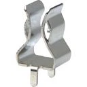
Bring the populated board and enclosure together
Start with the current assembly, enclosure pieces, fitted fasteners, drawings and the intended fuse and clips. Ask the board owner to mark the drawing revision and which component heights or cable positions are most likely to affect the space. Look at nearby tall parts, terminal blocks, internal dividers, wire bundles and labels. Remove any temporary bench brackets that will not be present in service and install the parts that will. A useful test begins with the intended mechanical state.
Photograph the area from above and from the opening a person will actually use. A fuse may be accessible vertically on a sample bench but obstructed at an angle in the assembled enclosure. Establish whether service is expected on the installed unit, after removing a cover or after withdrawing a board assembly in an approved procedure. Different service assumptions change the mechanical design. Agree which case the prototype sign-off represents before declaring the area accessible.
Measure both the envelope of the installed fuse and the movement needed to remove it. In a close layout, the extraction tool may need more room than the cartridge itself. Verify direction and keep-out regions at both ends. Mark what the technician or tool can safely touch under the approved procedure. If neighboring wiring can be routed in two ways, assemble the allowed worst case and document any route constraint that needs to become a production instruction.
Confirm the footprint before blaming the enclosure
Use the exact component drawing to check mounting centers, seating height, terminal style and fit to the board footprint. Do not extrapolate from nominal fuse length alone. On a pair of clips, the installed position affects cartridge fit. Compare the joint between clip and board, where the fuse ends sit and whether the cartridge can reach its intended installed position without visible damage or unintended loading. If the assembly uses approved production soldering or fastening, use a representative installed sample for validation.
If the cartridge feels unusually tight or loose, capture the sample identity and compare clip spacing, orientation and fuse dimensions with approved drawings. Keep reference parts in their identifiable packaging. Do not rework a clip simply to make the first sample fit and then consider the original design released. A customer receiving parts needs drawings and accepted references that enable repeating the fit, including production variation agreed by engineering.
| Mechanical check | Evidence to keep | Result to escalate |
|---|---|---|
| Board installation | Fit drawing, clip orientation, terminal and seating photos | Misaligned or incompletely seated terminal |
| Cartridge access | Video or photos from the actual service opening | Tool interference or abnormal contact |
| Enclosure fit | Assembly revision, covers, cable route and measured clearances | Cover touches fuse assembly or tool path |
| Repeat check | Sample identities, observations and approved cycle method | Loose mounting, changed fit or visible damage |
Watch how the replacement actually happens
With the unit confirmed de-energized and the approved service method available, have an authorized person show how the specified removal tool reaches the fuse and where the cartridge goes as it leaves the clips. Use normal work angles and avoid forcing contact. Observe whether a hand or tool needs to pass too close to a component or whether the installer needs a different movement than the design assumed. Record the mechanical objection for the responsible engineer to resolve.
Fit the specified replacement and recheck that it reaches the intended seated position. If the clip or holder supplier provides a defined mechanical test method, use the applicable procedure for any required repeat trial. Where there is no approved cycle criterion, document the demonstration as a fit review. Do not invent an allowable force or endurance limit from one sample. Take photos before and after and record any visible changes to the board, terminals, enclosure, wires or holder.
Consider how the correct replacement will be identified later. An accessible holder can still be difficult to service if labels are hidden by wiring or the approved fuse code appears only on a document inaccessible in the field. Put the service identifier where it can be read in the intended state. Keep the rated replacement and the access procedure in the product's controlled records rather than sending technicians to compare appearances on a distributor page.
Turn the test into drawing changes and receiving evidence
Separate findings by owner. Board layout controls footprint and keep-outs. Mechanical design controls enclosure and access. Purchasing controls part identity and acceptable substitutions. Assembly controls orientation and representative installation. If the issue can be closed with a routing change, attach the updated drawing and photos, then repeat the relevant access check. If the problem follows a vendor component, obtain the data and look at another approved sample before releasing or rejecting material.
For a pilot, keep one accepted configuration with the board, clip, fuse and housing revisions. Ask the supplier to confirm the exact purchased clip, any applicable application information and how the shipment will be identified. Incoming staff should have the drawing or marked record needed to distinguish a visually similar alternate. Schedule a separate approval for electrical ratings, protective coordination and any necessary functional trials, which should follow the responsible product engineer's approved plan.
Before the first PCB fuse holder fit test, keep a small reference pack with the exact cartridge, manufacturer drawing and intended mechanical stack. Ask production to take footprint measurements from an installed board and document which features are difficult to inspect after the enclosure is assembled. For fuse clip footprint verification, a photo with one reference scale can support a finding, but the released drawing and the specified measurement method should control dimensions. Record the populated board service clearance with wires in the approved routing condition and the enclosure in the intended service state. During the fuse removal trial, also note where the tool and removed fuse can be placed without disturbing approved adjacent parts. Add those observations to the PCB holder mounting sample record with the assembly and accessory revisions. If the service team recommends a change, have engineering mark its impact on the part specification and the assembly drawing. Preserve the updated photos so receiving can verify what was approved, then close the mechanical issue separately from the protective circuit review.
Use two drawings during the service demonstration: the released assembly showing the installed part, and a simple marked view showing the tool path. A first-article reviewer can use the second view while recording the movement. When a layout issue is corrected, retain both old and new references and record which product build used the new version. Production can then avoid applying the fix to the wrong enclosure.
Fuse fit and service questions
Does a 6.35 × 32 mm marking define the PCB footprint?
Obtain the holder or clip drawing and the applicable fuse data. The designation describes a cartridge format, while clip terminals and PCB mounting requirements can vary. Check the exact pairing in drawings and on the intended assembly before ordering a lot.
Can I approve access without the enclosure?
Use an unenclosed board for early fit and assembly checks. Complete the service demonstration with the approved housing, neighboring parts and cable routing. Record the open bench and enclosure outcomes separately.
What should I do if the removal tool touches a nearby component?
Record which tool, step and installed part interfere. Stop the demonstration if the approved procedure cannot be completed. Ask the owner to review mechanical layout, tool choice or service route, then repeat the relevant test with the released change.
How many replacements should the bench demonstrate?
Use the number and method specified by the applicable approvals where available. For an initial fit review, document what was actually demonstrated. If the project needs evidence of repetitive service, agree a controlled method before making any endurance statement.
Does a good clip fit establish current rating?
Keep mechanical validation separate. Electrical ratings, circuit requirements, temperature and other safety conditions need review using the applicable data and approved methods. Use mechanical sign-off as a component of the overall release.
What details help when requesting another clip sample?
Send the exact cartridge, PCB drawing revision, mounting style, available clearance, enclosure access direction, and application requirements. Include marked photos if the previous sample interfered. Ask the supplier to identify the proposed clip and its drawing.
Request a clip sample
Send XC Electronics the cartridge reference, board footprint, populated-board and enclosure details, service clearance and electrical requirements. Ask for the closest matching clip drawing and a sample for your approved fit and electrical checks.